KLST_SHEEP Board
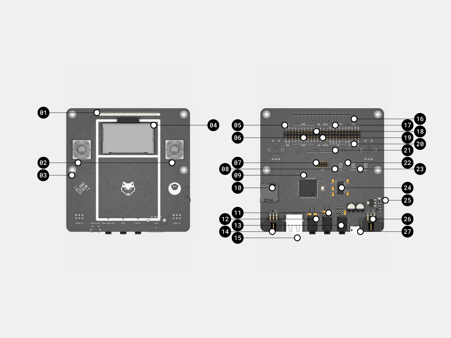
KLST_SHEEP (v0.1) is a hand-held-sized development board with a TFT-Display, 2 push-button encoders, 16 LEDs and 2 serial ports, based on STM32H743VI MCU. it aims to facilitate the development of smaller audio applications. the board can be connected to other KLST_SHEEP boards via the serial IDC connector. it can be programmed via the Arduin IDE through the USB connector ( DFU mode ) or with an external programmer ( SWD mode ).

| # | FUNCTION | DESCRIPTION |
|---|---|---|
| 01 | 16 programmable LEDs | LED_00 – LED_16 user programmable + dimmable LEDs |
| 02 | 2× rotary encoders | with push buttons |
| 03 | 4× mounting holes | M3 diameter |
| 04 | Display Connector | mount for SPI connection to TFT display, usually fitted with a 2,8” TFT display with 240×320px resolution |
| 05 | 3.3/5V power pins | power in-+output pins. can either be used to power the board or to power peripherals if board is powered via USB |
| 06 | 16× GPIO pins | programmable GPIO pins, 3.3V tolerant only |
| 07 | JTAG/SWD interface | 14-pin interface for external programmer ( e.g STLINK-V3 ) includes a dedicated serial debug line |
| 08 | programmer button | sends board into DFU mode ( LEDs blink in pattern ) |
| 09 | STM32H743VI MCU | microcontroller ( MCU ) with 480MHz, 864KB RAM, 2048KB Flash |
| 10 | SD card reader | Micro SD card reader, SPI-based |
| 11 | audio input, line-in | 3.5mm, line level input for audio signals ( e.g vconnection to computer audio output ) |
| 12 | audio output, line-out | 3.5mm, line level output for audio signals ( e.g connection to HiFi systems ) |
| 13 | headphones + mic | 3.5mm, 3 ring audio jack with stereo output and mono input. can be used to connect e.g a headset. |
| 14 | IDC connector w/ power + UART | SERIAL_01, can be used to connect e.g to other KLST_SHEEP boards, see 26 |
| 15 | USB-A | USB port for connecting USB Devices to board as USB host e.g computer mouse or keyboard |
| 16 | 1× I2C | I2C interface |
| 17 | 1× SPI | SPI interface, also used in Display Connector see 04 |
| 18 | 2× ADCs + 2× DACs | additional ADCs + DACs w/ 12BIT resolution |
| 19 | audio in-+output + line-in+out | same as 11 + 12 |
| 20 | 1× UART ( serial ) | pin out for serial port, same ports as 07 |
| 21 | 1× SPI | SPI interface |
| 22 | reset button | resets board |
| 23 | boot flash button | select boot mode. if button is held down during reset board starts in DFU mode |
| 24 | WM8731 Audio Codec | audio DAC+ADC w/ 16BIT resolution and up to 48KHz sampling rate |
| 25 | power LED | |
| 26 | IDC connector w/ power + UART | SERIAL_00 can be used to connect e.g to other KLST_SHEEP boards, see 14 |
| 27 | USB-B micro + PWR | USB port for connecting board as USB device. can also be used to program and power the board |
Debugging
KLST_SHEEP features a dedicated serial port for debugging which is connected to the STLINK-V3 programmer. once connected to a computer the programmer creates a virtual serial port ( e.g on macOS it might look like this /dev/tty.usbmodemXXXXXXX ).
this port can be used e.g to exchange debug information with a USB Host e.g a computer running the Arduino application.
the example program below can be used to test the serial port:
#include "Klangstrom.h"

void setup() {
    Serial.begin(115200);
}

void loop() {
    Serial.println(".");
    delay(1000);
}
the 2 UART ( serial ) ports as well as the USB Device port can be used for other applications in parallel.
Feature List
- STM32H743 MCU with 480MHz, 864KB RAM, 2048KB Flash
- WM8731 audio codec with 2× audio DAC + 2× audio ADC ( 16/24BIT )
- 1× LINE OUT ( stereo )
- 1× LINE IN ( stereo )
- 1× HEADPHONE + MIC ( mono )
- 2× ADC ( 12BIT, opt 6 extra channels )
- 2× DAC ( 12BIT )
- 2× UART ( serial )
- 16× GPIO
- 1× USB Host
- 1× USB Device ( + Power Supply )
- 1× I2C
- 1× SPI
- 2× rotary encoders with push buttons
- 16× programmable LEDs with PWM + 1× power LED
- 1× SD card reader
- 1× JTAG/SWD interface + serial debug ( 14-pin )
- programmer + reset + boot flash buttons
- 4× Mounting Holes
Errata
see Known Issues ( Application )